The School of IoT
Why we should choose SOI?
It's an All-in-One board where different types of modules such as Wi-Fi, Bluetooth, relay, buzzer, etc., are included and it works like a microcontroller like an Arduino. Anyone can do all that with the School of IoT board. This high-quality board is a one-for-all solution that instantly boosts any Iot-demanding system.
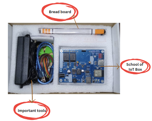
Components of School of IOT Box
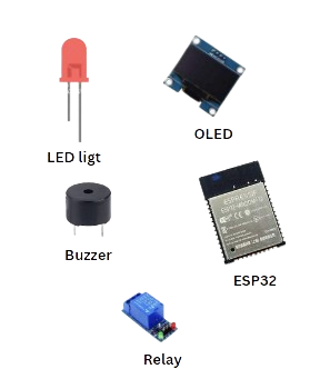
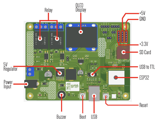
Short description of Basic Tools of SOI BOX
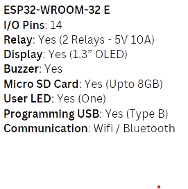
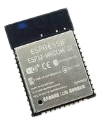
ESP32-WROOM-32 E:
ESP32-WROOM-32E is a powerful, generic Wi-Fi + Bluetooth + Bluetooth LE MCU module that targets a wide variety of applications. Ranging from low-power sensor networks to the most demanding tasks, such as voice encoding, music streaming, and MP3 decoding.
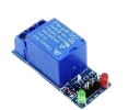
Relay:
A relay is an electrically operated switch. It consists of a set of input terminals for single or multiple control signals, and a set of operating contact terminals.
Buzzer:
Buzzer is a kind of voice device that converts audio models into sound signals. It is mainly used to prompt or alarm

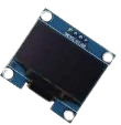
Display:
This is a 1.3-inch blue OLED display module. The display module can be interfaced with any microcontroller using SPI/IIC protocols. It is having a resolution of 128×64. The package includes a display board, a display, and a 4-pin male header pre-soldered to the board.
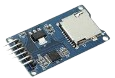
MicroSD Card Slot:
A Micro Secure Digital slot (MicroSD slot) is a small expansion slot located in mobile and other portable devices. It facilitates the increase of available memory via the insertion of a MicroSD card.
I/O:
I/O describes any operation, program, or device that transfers data to or from a computer.
User LED:
USER LED (Light Emitting Diode) is an electronic device, which emits light when the current passes through its terminals

Let's Talk About some Sensors!!!!
What is a sensor?
Sensors are devices that detect and measure physical phenomena, such as light, temperature, pressure, or motion, and convert them into electrical signals that can be interpreted by other devices or systems. They play a crucial role in various fields, including manufacturing, automotive, healthcare, and home automation. Using sensors we can make some projects like LED control. smart gardening, automotive home, fire detection, etc.
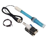
pH sensor:
A pH sensor is a device used to measure the acidity or alkalinity of a solution. It measures the hydrogen ion concentration (pH) in a solution and converts the reading into a voltage that can be read by a microcontroller or other electronic device. pH sensors are commonly used in applications such as water treatment, agriculture, food and beverage production, and scientific research. They are typically made of a glass electrode and a reference electrode that is immersed in the solution being tested. The glass electrode measures the pH of the solution, while the reference electrode provides a stable voltage reference. pH sensors can provide accurate and reliable readings when calibrated properly, and are an essential tool in many industries and fields of study.
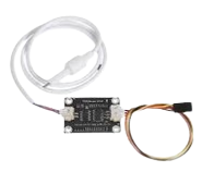
TDS Sensor:
A TDS meter is a small hand-held device used to indicate the Total Dissolved Solids in a solution, usually water. Since dissolved ionized solids, such as salts and minerals, increase the conductivity of a solution, a TDS meter measures the conductivity of the solution and estimates the TDS from that reading.
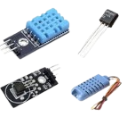
Temperature Sensor:
The definition of a temperature sensor is essentially an electronic device used to take accurate temperature measurement readings.
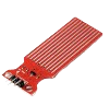
Water Level Detector:
Level sensors are used to detect the level of substances that can flow. Such substances include liquids, slurries, granular materials, and powders. Level measurements can be done inside containers or it can be the level of a river or lake.
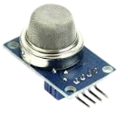
Gas Sensor:
Gas Sensor: A gas sensor is a device that detects the presence of different gases in the air and provides an indication of their concentration levels. It is commonly used in various industries to monitor and control air quality, safety, and environmental conditions.
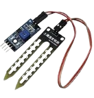
Moisture Sensor:
A moisture sensor is a device that measures the amount of moisture present in a substance or environment. It is commonly used in agriculture, construction, and other industries to ensure proper moisture levels for optimal results.
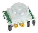
Motion Sensor:
A motion sensor is a device that detects movement in a specific area and can trigger an action, such as turning on lights or activating an alarm.
LDR Sensor:
An LDR sensor, or Light-Dependent Resistor sensor, detects and measures the amount of light in a particular environment. It works by changing its resistance in response to the amount of light present and can be used in a variety of applications such as automatic lighting systems and optical communication devices.

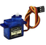
Servo Motor:
A servo motor is a type of motor that is commonly used in robotics and automation. It is designed to accurately control the position, velocity, and acceleration of a mechanical system. This is achieved through a closed-loop control system that uses feedback from sensors to adjust the motor's output. Servo motors are widely used in applications such as CNC machines, 3D printers, and robotic arms.
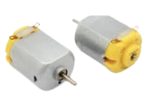
Dc Motor:
A DC motor is a type of electric motor that converts direct current electrical energy into mechanical energy through the interaction between a magnetic field and current-carrying conductors.
Arduino IDE Installation Process
Go to Arduino Website: Download Arduino
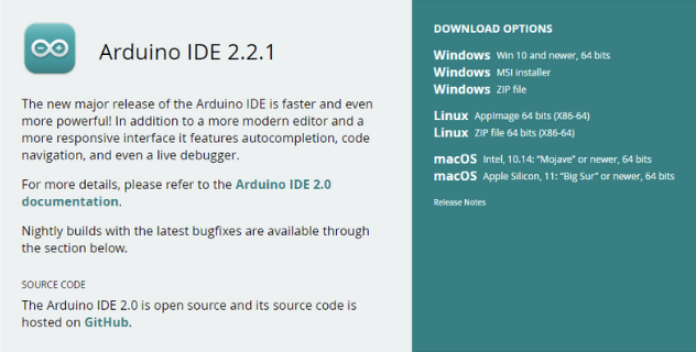

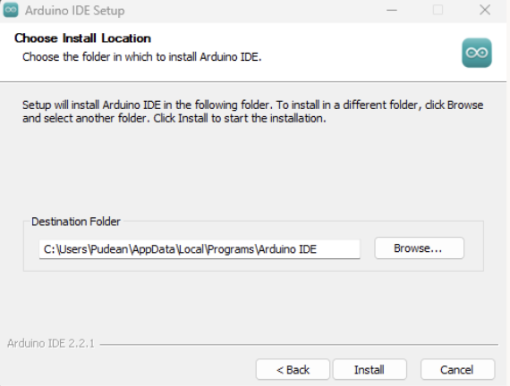
Follow the Installation Progress According to the link Installation Progress
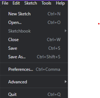
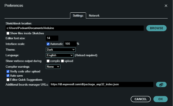
In your Arduino IDE, go to File → Preferences (Ctrl+Comma)
Click the link on Additional Board Manager, Then Click the “Ok” button.
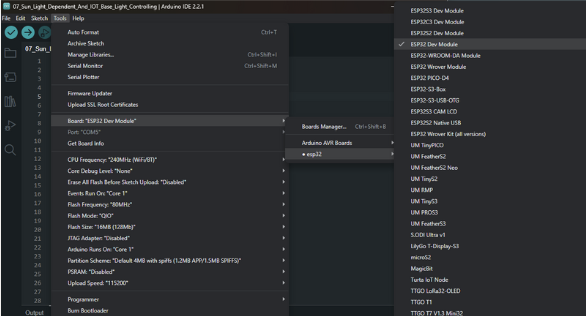
Open the Boards Manager. Go to Tools → Board → Boards Manager
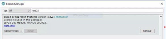
Search for ESP32 and press install button for the “ESP32 by Espressif Systems”:
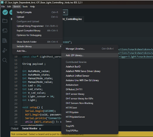
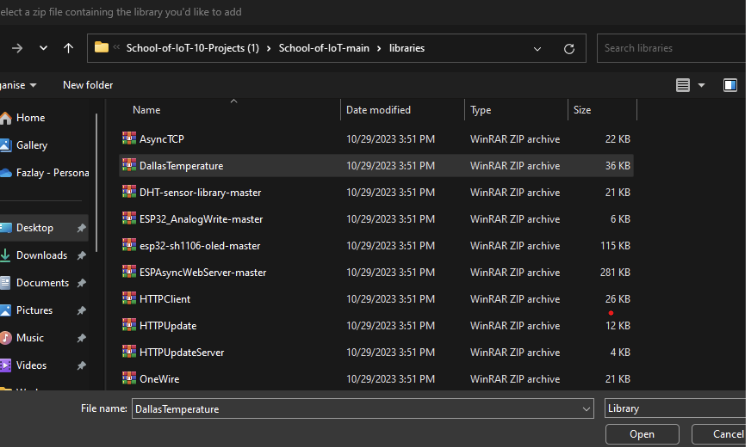
Click the link to download the library files for the sensors, Copy the library files in your destination folder in library section. Then , Open Sketch → Include Library → Add .Zip Library → Select the zip file containing the library you would like to add.
What is IoT Server?
An IoT server is a software platform that connects and manages Internet of Things (IoT) devices, allowing them to communicate with each other and transmit data over the internet. It provides the necessary infrastructure for IoT applications to function and enables remote monitoring, control, and data analysis.
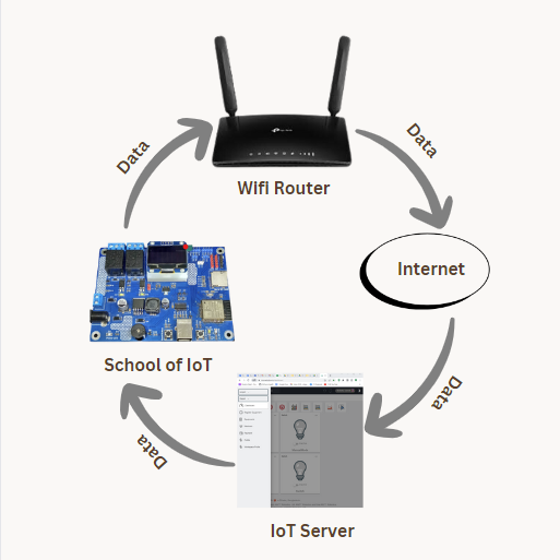
IoT Work Flow
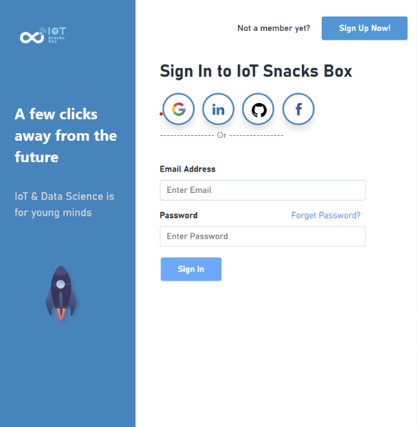
IoT Sign UP Page
1. Open a web browser and log in https://iotsnacksbox.io/
2. Click on Sign up button
3. Fill up necessary requirements.
4. Check the Terms & Conditions box and then Click on the ‘Account Create’ button.
IoT Server Dashboard
Log in to iotsnacksbox web dashboard and you find this interface.
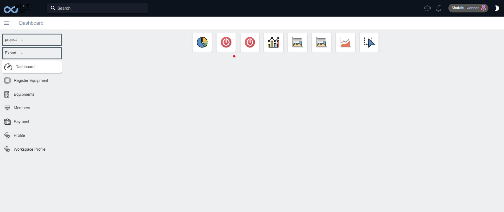
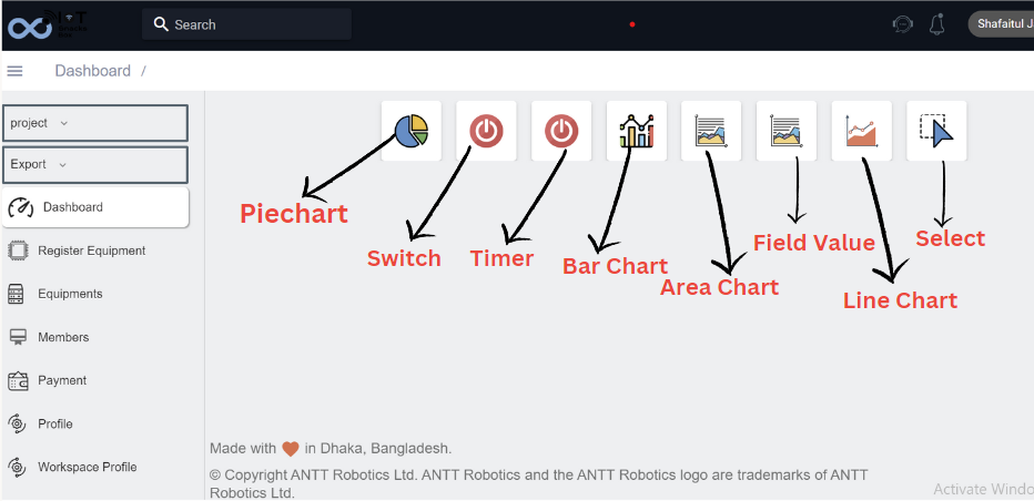
IoTSnacksbox Dashboards & Widgets

This is called Pie chart. The “pie chart” is also known as a “circle chart”, dividing the circular statistical graphic into sectors or sections to illustrate the numerical problems. Each sector denotes a proportionate part of the whole. To find out the composition of something, Pie-chart works the best at that time.

This is called Switch. The switch is mounted atop the dashboard and controls the activation of a function. The switch widget is great for simply turning something ON or OFF. Can be linked with a Boolean variable. An example of how it is used in a sketch:
This is called Timer. The timer is mounted atop the dashboard and controls the action to be fired. One can pick a start & end date for when the variable should be triggered, and for how long it should be active. This variable can be controlled in real time using a graphical widget that you can place on the dashboard.

A bar chart is a way of summarizing a set of categorical data. The bar chart displays data using a number of bars, each representing a particular category. The height of each bar is proportional to a specific aggregation ; for example the sum of the values in the category it represents.

An area chart is a graph that combines a line chart and a bar chart to show changes in quantities over time. It’s similar to a line graph in that data points are plotted and connected by line segments. It is used to track real time data, as well as tracking historical data.

A line chart is a graphical representation of an asset's historical price action that connects a series of data points with a continuous line. The chart widget is great for data analytics. This widget can for example be used to track temperature changes, energy consumption and other sensor values. A chart widget can only be linked to one variable at a time.
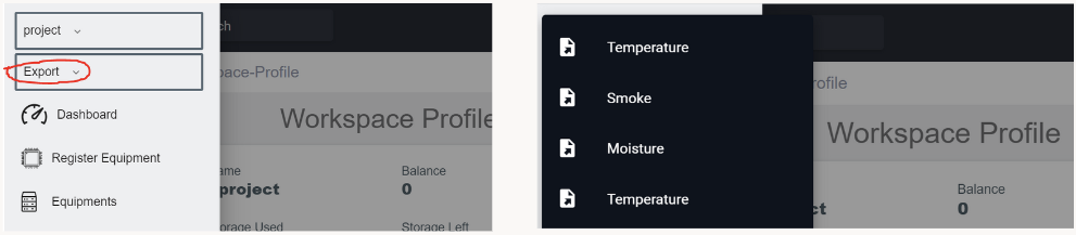
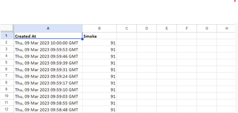
How to Download and Interpret projects data from the IoTsnacksbox Dashboard
Click the Export option and choose any project you made. The Data will automatically download after choosing. Open download folder by Excel or google sheets to see the real time data with date, time and percentage. Follow the image to show the interpreted data;
LET'S EXPLORE SOME PROJECTS VIA SOI COMPONENTS AND SENSORS
PROJECT 1: LED CONTROL
CIRCUIT DIAGRAM DESIGN
Nowadays, household gadgets are being made ‘smart’, usually by using your Wi-Fi to connect to an app on your smartphone or tablet, allowing you to control them remotely. How about controlling the lights with the help of IOT? This will not only make your life easier but also lessen the wastage of electricity. Consider the street lights which require manual switching. By remotely controlling the lights with the help of IOT, we can make this task easier.
What you need for this Project :

School of IoT box
2 LED
Few jumper wires
Two 220 ohm resistor
One Breadboard
First connect two LEDs with the School of IoT box. Connect two 220 ohm resistors with one end to the anode pin of each of the two LEDs
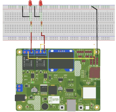
Connect the other end of two resistors with the jumper connector wires to the NO pin of two separate relays in the School of IoT box.
Connect the ground pins of the School of IoT box to the cathode pins of the two LEDs.
Now connect the COM pins of the two relays to the 5-volt pin of the School of IoT box.
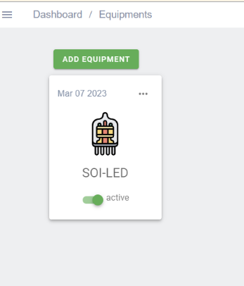
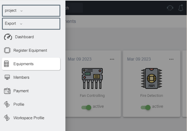
Log in to iotsnacksbox web dashboard. Click on to ‘Equipment’ on the left side panel
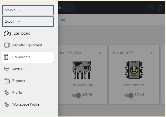
Then click on the ‘Add Equipment’
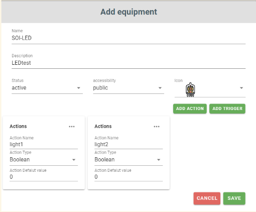
Add equipment, fill up the name, Add action and save. You have to write the action or tigger name as per the code. Both name must be same. Action type will be Boolean and Action Default value will be 0
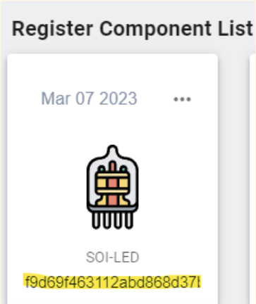
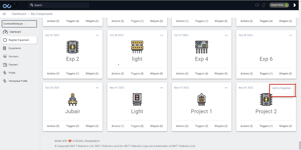
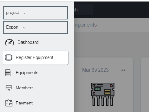
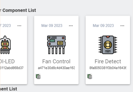
Click on ‘Register Equipment’ of the left side panel. Then find your component. Then Click upper side of that box ‘Add Register’
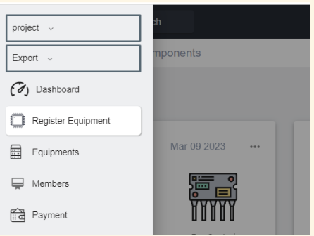
Enter a registry name. Then click on ‘Submit’ button. Click on ‘Register Equipment’ on the left side panel then you will find your Register Component as well as a copy icon (on the below right side) will be added in that Register Component box.
Code Link
Enter this link through a web browser. Then you will enter the
project folder at the link according to your project title and
download that project file. The file is named “ .ino”. If you
open that file through the Arduino app, you will see the
programming code. Let’s edit the code as we have bulit the
circuit
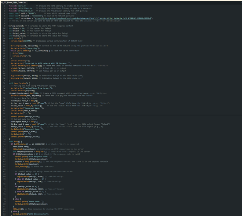
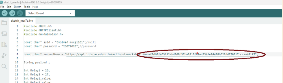
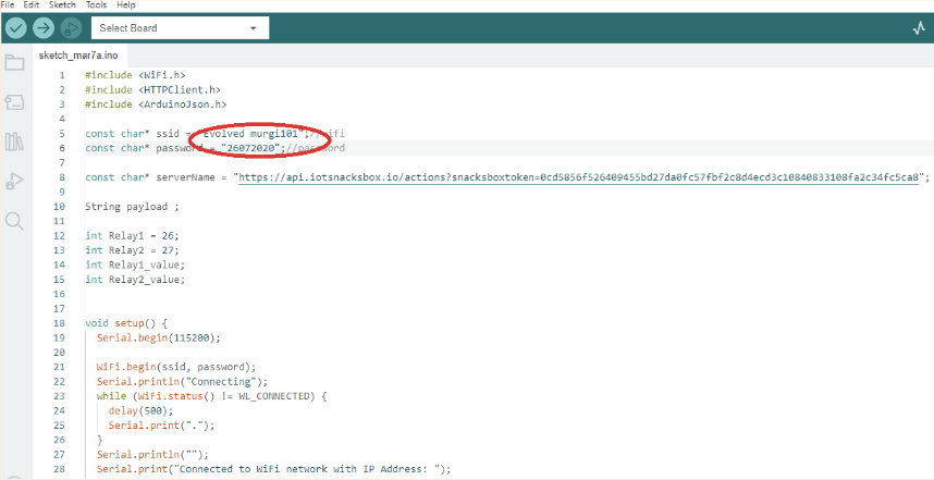
Then please type your wifi id & password on ‘ssid= ’ & ‘password= ’ section with proper spelling.
Go to ‘Register Equipment’ and click on the copy icon. This means that you copy your unique API Integration code. Go to Arduino code and paste that API in here.
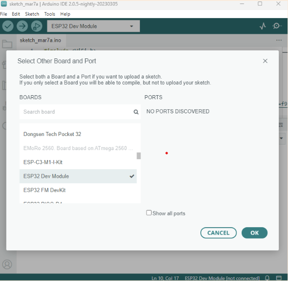
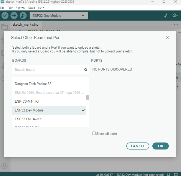
Powered on your School of IoT board by adapter & Plug USB cable on your School of IoT board with your laptop. Then, select Tools → Board → ESP32 Dev Module from the menu bar of Arduino App then you must select the appropriate port from Tools → Port and you must select the appropriate upload speed 115200 from Tools → Upload Speed → 115200 Now you can upload your programming code.
After uploading the code then open the Serial Monitor of Arduino app. Then if you wait a few moments, you will see this kind of message.Now go to the dashboard. Active switch button of light1 & light2. Then you will notice that both the LEDs are turned on according to your instruction.
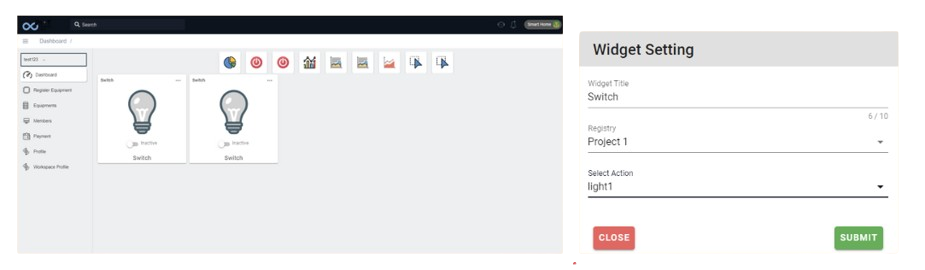
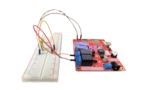
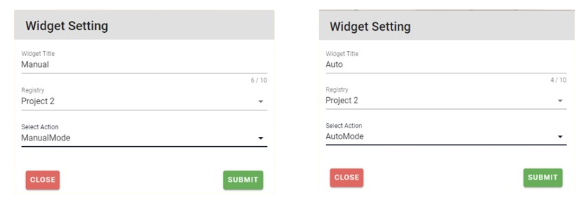
Final Output: Now go to the dashboard. Select switch and drag the swich in the middle and we have to set up the Widget. As we are using it as a switch give it a title and select the registry which is your registered one and in action we have to select light1 or light 2 as per our registry setting and code. Now we have the active switch button of light1 & light2. Then you will notice that both the LEDs are turned on according to your instruction. Real picture of project 1 according to the circuit diagram, Switch configuration, widget setting and serial monitor of how it works:
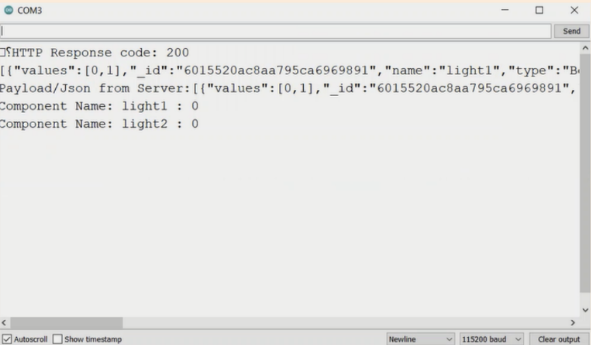
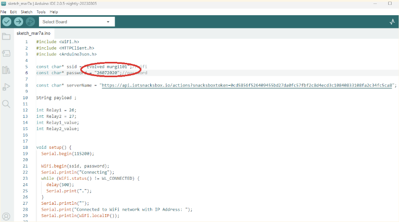
In this output and explanation:
1. The device successfully connected to the Wi-Fi network with
an IP address of 192.168.0.112. 2. An HTTP GET request to the
server resulted in a response with a status code of 200
(indicating success). 3. The response is a JSON array
containing two objects, each representing a component: -
"light1" with a value of 1 (indicating it's turned on). -
"light2" with a value of 1 (indicating it's turned on). 4. The
code then prints the received JSON payload. 5. The
`Json_Parsing` function is called to parse the JSON data and
extract the component names and their values. 6. The component
names and values are printed to the serial monitor.
Real-time Implementation of LED Control
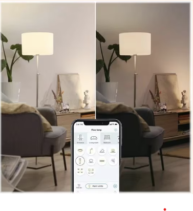
With smart lighting becoming popular among modern homeowners, it’s not surprising that you may be looking to install some in your own home. After all, you’ll have complete control over how you light your home, increasing convenience, all while still being more energy-efficient and having better security.
PROJECT 2: FAN CONTROL
CIRCUIT DIAGRAM DESIGN
Attempts to reduce the hardships of human workers have been going on for a long time. With almost everything being made smart, the need for a smart home is increasing with every passing day. Being able to control a fan or AC remotely will not only make human life easier and more comfortable, but this will also be very useful for the paralyzed or sick people too when people are not able to get up and manually switch the fan ON/OFF. Automating the fans based on room temperature will not only reduce human effort but also reduce electricity wastage and save money.
What you need for this Project :
School of IoT box
Fan
Few jumper wires
DHT11
One Breadboard
Take one DHT11 Sensor and one DC Fan. First connect the DTH11 module to the School of IoT.
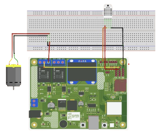
Connect the 5 volt pin of the module to the 5 volt pin of the School of IoT. Connect the ground pin of the School of IoT to the ground pin of the module.
Connect the IO13 pin of the School of IoT to the DHT11 Sensor module's signal pin using the jumper wire. We setup the code as we have connected it.
Then connect with a relay of the School of IoT to the fan or AC. Let’s consider a DC fan for this experiment. Connect the NO pin of the relay to the positive wire of the DC fan. Then connect the 5 volt pin of the School of IoT to the COM pin of the relay.
Log in to iotsnacksbox web dashboard. Click on to ‘Equipment’ on the left side panel
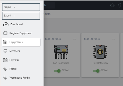
Then click on the ‘Add Equipment’
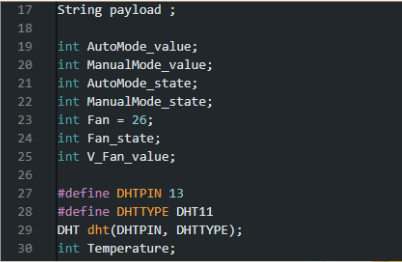
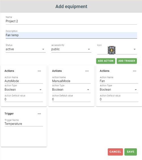
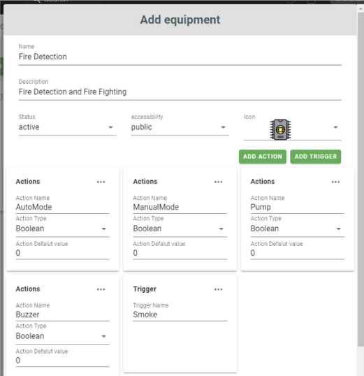
Add equipment, fill up the name, Add actions and trigger and save. We are using two modes here AutoMode and ManualMode. Temperature as trigger to turn the fan on or off.
Click on ‘Register Equipment’ of the left side panel. Then find your component. Then Click upper side of that box ‘Add Register’
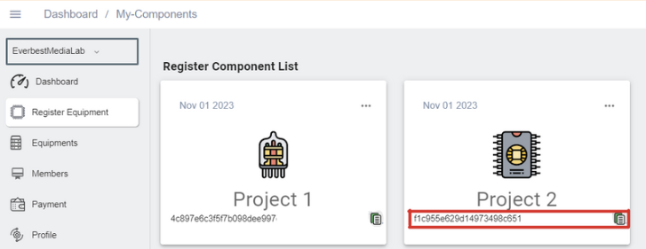
Enter a registry name. Then click on ‘Submit’ button. Click on ‘Register Equipment’ on the left side panel then you will find your Register Component as well as a copy icon (on the below right side) will be added in that Register Component box.
Code Link
Enter this link through a web browser. Then you will enter the project folder at the link according to your project title and download that project file. The file is named “ .ino”. If you open that file through the Arduino app, you will see the programming code
Then please type your wifi id & password on ‘ssid= ’ & ‘password= ’ section with proper spelling.
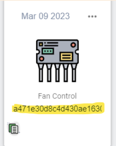
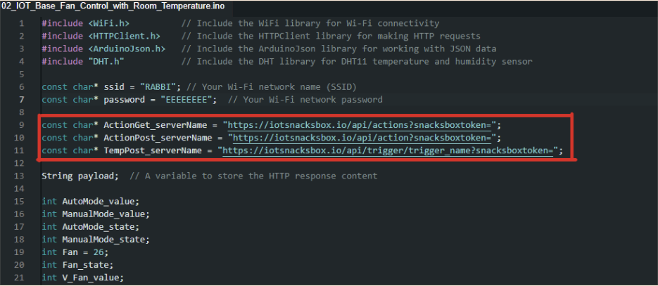
Go to ‘Register Equipment’ and click on the copy icon. This means that you copy your unique API Integration code. Go to Arduino code and paste that API in here. We also have to change the trigger name.
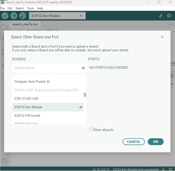
Powered on your School of IoT board by adapter & Plug USB cable on your School of IoT board with your laptop. Then, select Tools → Board → ESP32 Dev Module from the menu bar of Arduino App then you must select the appropriate port from Tools → Port and you must select the appropriate upload speed 115200 from Tools → Upload Speed → 115200 Now you can upload your programming code.
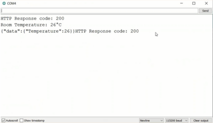
After uploading the code then open the Serial Monitor of Arduino app. Then if you wait a few moments, you will see this kind of message. Now go to the dashboard. Active switch buttons Then you will notice that both the pump and Sensor are turned on according to your instruction.
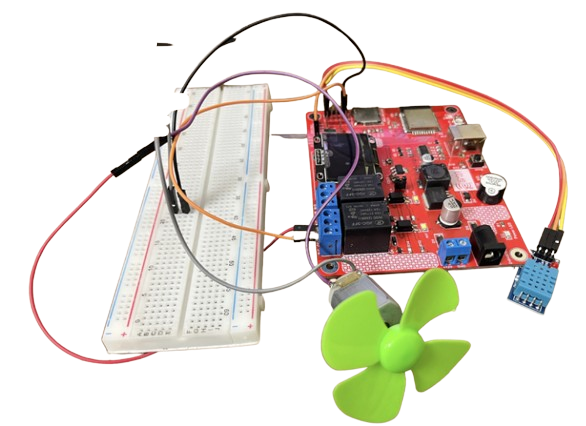
In the dashboard, We have to add 3 switches Automode, ManualMode, Fan and a pie chart to that will show the temperature value. We have to setup the switches and pie chart shown as figure 46. Now active auto mode. You will observe that automatically your fan is on or off as your requirement. Then inactive auto mode then active manual mode. Now you can manually control your fan. Real picture of project 2 according to the circuit diagram and serial monitor of how it works :
Real-time Implementation of Fan/AC Control
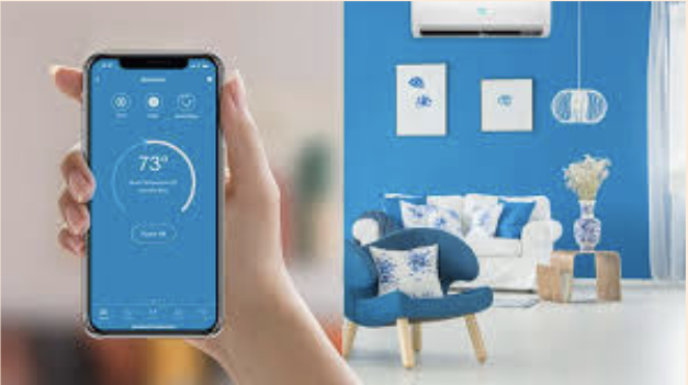
Smart ceiling fans allow you to control them from anywhere using a smartphone/remote via Wi-Fi or Bluetooth technology, rather than having to pull a chain or flip a switch on your wall. You may set up automated schedules and control your ceiling fan with light from anywhere with the touch of a button.
PROJECT 3: FIRE CONTROL
CIRCUIT DIAGRAM DESIGN
Every year, thousands of people die due to fire accidents. Those lives might have been saved if the fire was detected in time. This is why every building should have fire detection and fighting systems to prevent the sufferings and losses caused by fire hazards. A fire detection and the fighting system will detect the occurrence of an event that may result in a fire and send a signal as an alarm. Then it will also activate the water pump to prevent the fire from spreading.
What you need for this Project :
School of IoT box
Fan
Few jumper wires
DHT11
One Breadboard
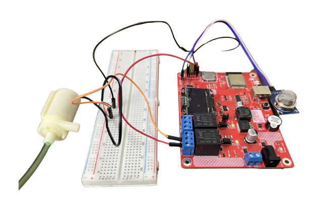
Take one Gas Sensor, and one DC Pump and already you have on board buzzer
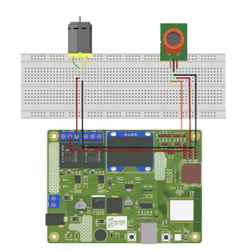
First connect the MQ-2 module to the IoT snacks box. Connect the 5 volt pin of the School of IoT to the module’s 5 volt pin using the jumper wire.
Connect the ground pin of the School of IoT to the ground pin of the module. Connect the IO39 pins of the School of IoT to the module's analog pin using the jumper wire. We setup the code as we have designed it. Buzzer is automaticlly bulid-in on pin 25
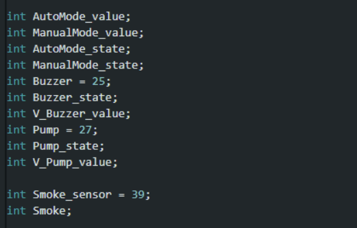
Then connect one relay of the School of IoTto the DC motor. Connect the NO pin of the 27th pin relay to the positive wire of the DC motor. Then connect the 5 volt pin of the School of IoTto the COM pin of the relay. Connect the ground pin to the School of IoT on the other end of the motor (negative wire).
Log in to iotsnacksbox web dashboard. Click on to ‘Equipment’ on the left side panel
Then click on the ‘Add Equipment’
Add equipment, fill up the name, Add actions and trigger and save
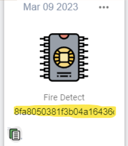
Click on ‘Register Equipment’ of the left side panel. Then find your component. Then Click upper side of that box ‘Add Register’
Enter a registry name. Then click on ‘Submit’ button. Click on ‘Register Equipment’ on the left side panel then you will find your Register Component as well as a copy icon (on the below right side) will be added in that Register Component box.
Code Link
Enter this link through a web browser. Then you will enter the
project folder at the link according to your project title and
download that project file. The file is named “ .ino”. If you
open that file through the Arduino app, you will see the
programming code
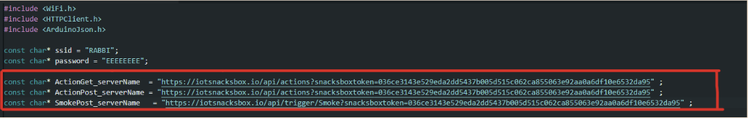
Then please type your wifi id & password on ‘ssid= ’ & ‘password= ’ section with proper spelling.
Go to ‘Register Equipment’ and click on the copy icon. This means that you copy your unique API Integration code. Go to Arduino code and paste that API in here. We do also have to change the trigger name.
Powered on your School of IoT board by adapter & Plug USB cable on your School of IoT board with your laptop. Then, select Tools → Board → ESP32 Dev Module from the menu bar of Arduino App then you must select the appropriate port from Tools → Port and you must select the appropriate upload speed 115200 from Tools → Upload Speed → 115200 Now you can upload your programming code.
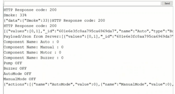
After uploading the code then open the Serial Monitor of Arduino app. Then if you wait a few moments, you will see this kind of message. Now go to the dashboard. Active switch buttons Then you will notice that both the pump and Sensor are turned on according to your instruction.
Final Output
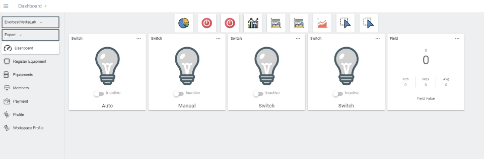
Now go to the dashboard. We have to add
AutoMode, ManualMode, Buzzer and pump as switch and a pie
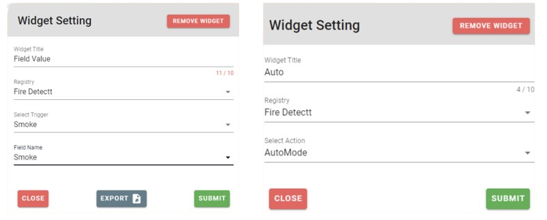
chart in which trigger will be the smoke. Change Field name,
select ‘Smoke’. Then you will notice smoke value in your
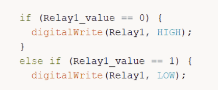
dashboard. If you look at the code, you will notice that there
are two levels of ‘Smoke Value’ for the gas sensor. Low and
high. Active auto mode. If there is low level gas or smoke, no
horn will alarm and the pump will be off. If there is a high
level of gas or smoke, the horn will alarm and the pump will
turn on 53 immediately. Inactive auto mode and active manual
mode. Now you can manually control your pump.
Real-time Implementation of Fire Detection and Fire Fighting System
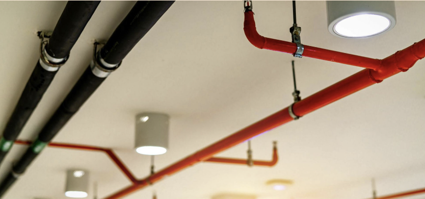
A deluge sprinkler system releases water from each sprinkler when a fire alarm is triggered and is used in facilities where flammable or combustible liquids present a high risk of fire. Other fire suppression systems have minimal cleanup and damage due to local activation. Along with other active and passive fire protection measures, like cable fireproof coating, the system can help suppress smoke and flames and reduce fire spread, reducing damage and giving everyone time to leave the facility when firefighters arrive safely.